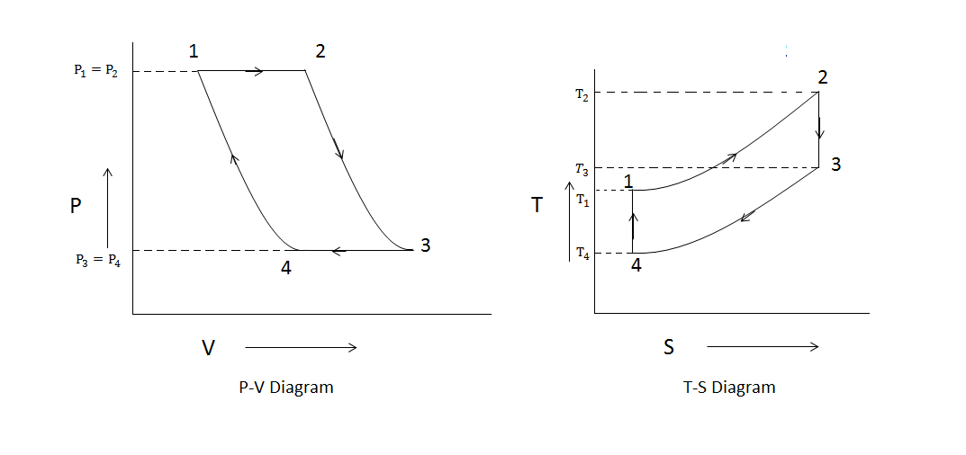
Brayton cycle Gas turbine cycle application: everything about gas turbine working Turbojet vs. turbofan: safety, efficiency, and performance – airplane
Gas Turbine Combined Cycle Power Plant System Schematic
Turbine cycle linquip Brayton thermodynamic turbojet turbofan thrust pv pressure thermodynamics piston augmentation Brayton turbine pv reverse ericsson pressure cycles thermodynamic thermodynamics
Brayton cycle turbine gas closed engine diagram pv ideal thermal definition two
Closed cycle gas turbine: construction, working, diagramWhat is brayton cycle Turbine diagram gas cycle closed working pv various mechanical booster construction processes usedGas turbine combined cycle power plant system schematic.
Cycle turbine gas combined brayton ramjet thermodynamic nasa power engine plant thermodynamics non grc gov system result shock engineering wave .


Gas Turbine Cycle Application: Everything About Gas Turbine Working

Closed Cycle Gas Turbine: Construction, Working, diagram - Mechanical

Brayton Cycle - Gas Turbine Engine | Characteristics | nuclear-power.com

Turbojet vs. Turbofan: Safety, Efficiency, and Performance – Airplane

Gas Turbine Combined Cycle Power Plant System Schematic